1984-1988 Cluster Power Supply Repair
Video of this process
Symptoms of a defective Power Supply board
-
The backlighting doesn't light or lights intermittently, even after you've repaired the more common board connector issue.
-
Segments of the LCD panels flicker randomly (might be difficult to see without the backlight working)
-
The 5A LCD fuse blows with the cluster connected, and doesn't blow when the cluster is disconnected.
Troubleshooting the Power Supply
-
The schematic of the power supply for 1984-88 C4s is here: Click Here
-
Remove the 5-6 screws holding the metal back onto the digital cluster.
-
Physically examine the supply - look for charring, leakage, traces of smoke damage, etc. Fried electronics have a distinctive smell, so give it the sniff test. This can help you localize the problem.
-
See my article on Bench Testing the Cluster for info on powering up the cluster while it's out of the car.
-
Locate the 8 pin grey cable that connects the top board to the power supply. Measure the DC voltage between pins 1 and 6. It should measure +5.0V. If so, the power supply is likely working.
-
Measure the AC voltage between pins 1 and 6 of the grey cable. It should measure less than 50mV. If it's higher, the filter capacitors might have failed.
-
Measure the voltage between pins 1 and 3 of the cable that connects the power supply to the top board. This should be higher than 0. If it's not, the power supply is sensing that there is a problem on the power supply and shutting itself down.
-
Measure between pins 1 and 2 of the cable that connects the power supply to the top board - this should be +5V. If it's not, the problem is in the standby voltage regulator. Suitable replacements are available in our power supply rebuild kit.
-
If the power supply appears to be working correctly, the problem may be with the cluster and not with the power supply.
-
There are many electrolytic capacitors on the power supply. Age tends to cause the caps to dry out and short. This can cause the LCD and/or CLSTR fuses to blow. Suitable replacements are available in our power supply rebuild kit.
-
The power supply has a MOV between gnd and +12V. An overvoltage or reverse voltage can cause this to fail. This is a protective device, so if it's bad, it won't cause problems, but it leaves the cluster unprotected from power surges. If this is bad, it may be physically damaged/charred. A suitable replacement is available in our power supply rebuild kit.
-
If you have an oscilloscope, measure voltage across the input of the transformer. It should be a square wave approximately +12V pk-pk, 50% duty cycle, and 25KHz.
-
If you have an oscilloscope, measure the voltage at the collector of the switching transistor (the big three-lead thing glued to a capacitor). It should be a triangle or square wave of 50% duty cycle and ~25kHz. Measure the collector voltage. It should be the same 12Vpp, 25KHz square wave measured in the previous step.
-
The switching transistor (the transistor which is gooped to one of the electrolytic caps) freqently fails. We frequently see bad solder joints on this part and leads broken internally. A suitable replacement is available in our power supply rebuild kit. If you see a low voltage 25kHz signal at the base of the transistor and no corresponding 12Vpp square wave at the input side of the transformer, the transistor is likely the cause.
-
If you have an oscilloscope, measure the voltage at the output of the transformer. It should be a square wave of approximately 10Vpp, 25KHz, 50% duty cycle.
Rebuilding the Power Supply
We now sell a kit of parts to rebuild the '84-'88 power supply. It includes electrolytic capacitors to replace all in the cluster, a new switching transistor, +5V regulator for standby power, switching diode, Metal Oxide Varistor and more. This is a great way to save $80 over the cost of a new power supply.
Click Here for Power Supply Rebuild Kit

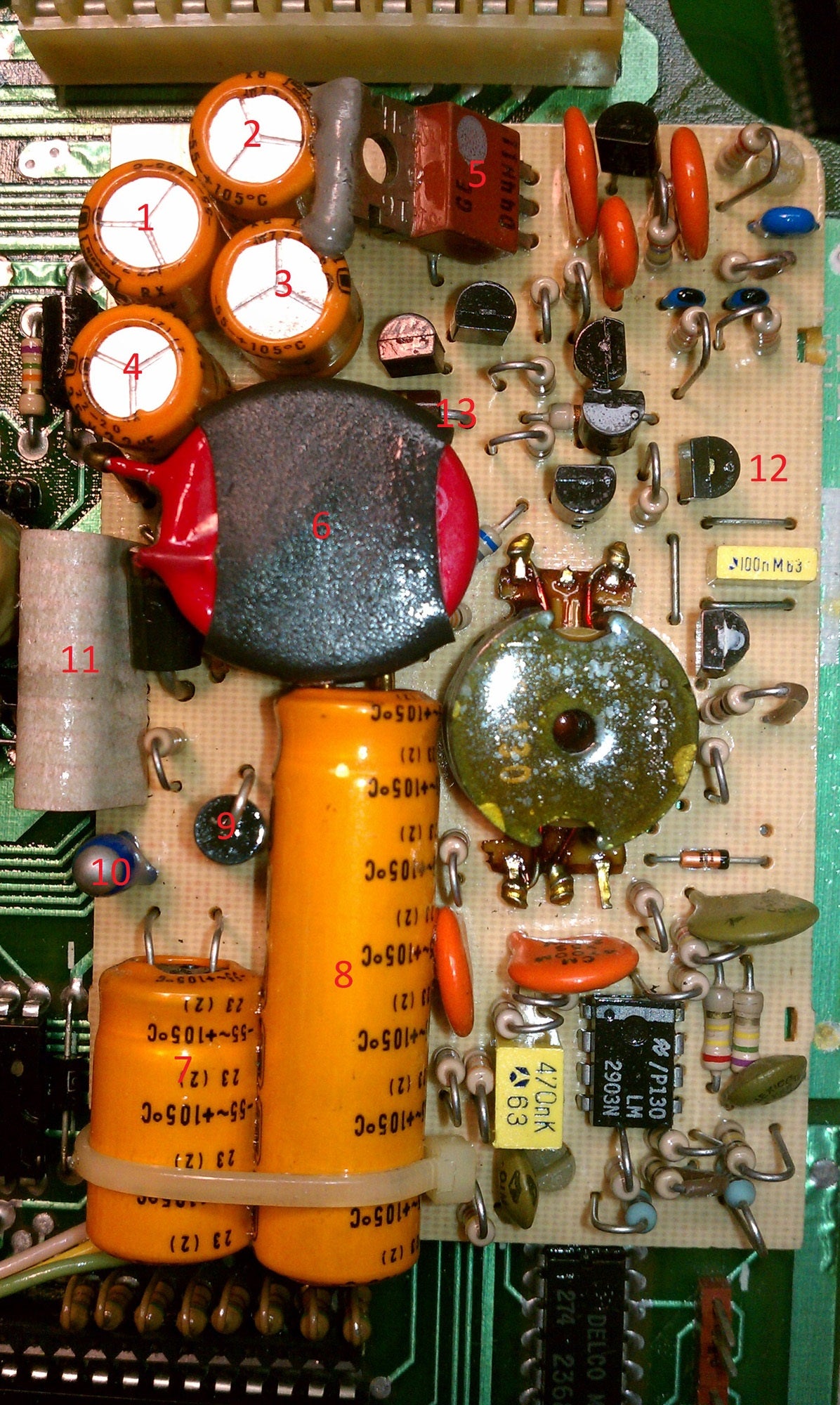
Locations where the new components should be installed
Cautions
-
The solder we included contains lead. Take reasonable precautions when handling it: Don't hold it with your mouth, don't breathe the solder fumes it creates, and wash your hands after handling the solder and before eating.
-
If the components have tape attached to the terminals, cut away the taped portion of the lead. Don't try to peel the tape off or the solder to the lead with tape residue - it won't work.
-
Desolder the flex cable which connects the power supply to the top board using desoldering braid or your favorite technique. It's easy to break this tuff by flexing it too many times while working on the power supply.
-
Remove the power supply from the top board carefully. Don't use a metal object to pry between the two boards. Lift the power supply board carefully. If it doesn't come off, cut the plastic board standoffs using wire cutters. We supply replacements in the kit in the event that you have to do this.
-
The kit contains the parts we commonly see needed in a power supply rebuild. You probably don't need to replace ALL of the components in the kit. If you end up needing components not provided in the kit, let me know and I'll attempt to find a source and include them with future parts kits.
Parts Replacement
Note: - The numbers on the images above correspond to the components in the list below.
-
Replace the capacitor marked 22uF. Be sure to mark the board with a sharpie to indicate the (+) and (-) terminals, and be sure to match the polarity markings on the new component to the markings you made on the board.
-
Replace the capacitor marked 22uF. Be sure to mark the board with a sharpie to indicate the (+) and (-) terminals, and be sure to match the polarity markings on the new component to the markings you made on the board.
-
Replace the capacitor marked 22uF. Be sure to mark the board with a sharpie to indicate the (+) and (-) terminals, and be sure to match the polarity markings on the new component to the markings you made on the board.
-
Replace the capacitor marked 22uF. Be sure to mark the board with a sharpie to indicate the (+) and (-) terminals, and be sure to match the polarity markings on the new component to the markings you made on the board.
-
If needed, replace the switching transistor. It's the only component in the kit which looks like the component shown in the image above. You can use hot glue to reattach the transistor to the capacitor.
-
If needed, replace the MOV - this is blue in the kit we sell. To remove it, you will need to cut the heat shrink, and reattach the new component with hot glue or another adhesive.
-
Replace the capacitor marked 330uF. Be sure to mark the board with a sharpie to indicate the (+) and (-) terminals, and be sure to match the polarity markings on the new component to the markings you made on the board.
-
Replace the capacitor marked 1000uF. Be sure to mark the board with a sharpie to indicate the (+) and (-) terminals, and be sure to match the polarity markings on the new component to the markings you made on the board.
-
Replace the switching diode. Be sure to install it with the cathode (white band) side facing up, and the other side facing the board.
-
Replace the Tantalum Capacitor. Be sure to mark the board with a sharpie to indicate the (+) and (-) terminals, and be sure to match the polarity markings on the new component to the markings you made on the board.
-
If needed, replace the cable that connects the power supply to the top board. It is possible to break the factory cable by flexing it back and forth too much. If yours breaks during the repair, replace it with the included cable.
-
If needed, replace the Standby Voltage Regulator marked 7805. Pay attention to the location of the flat side of this component, and be sure to reinstall the new component the same way.
-
The 150 Ohm resistor is located partially beneath the round disk component #6. If it is defective, replace the resistor.
If you have the ability, before you reinstall the power supply, power it up per the directions in the section above and test it.
Still Having Problems?
Unfortunately, cold solder joints, broken PC board traces and other random failures can also cause power supply failure. If the Power Supply Parts Kit fails to solve your power supply problems, we will credit the full price of the kit toward the purchase of a new power supply.
Replacing the Power Supply
We now offer a replacement power supply for the 1984-1988 Corvette Digital Instrument Panel.