1990-1996 Corvette Cluster Tach Analog Gauge Repair
Over time, vibration and heat can cause the analog calibration IC in your instrument panel to crack and change resistance, making the analog gauges go out of calibration or stop working. This process will replace this IC.

Signs your analog IC has failed
-
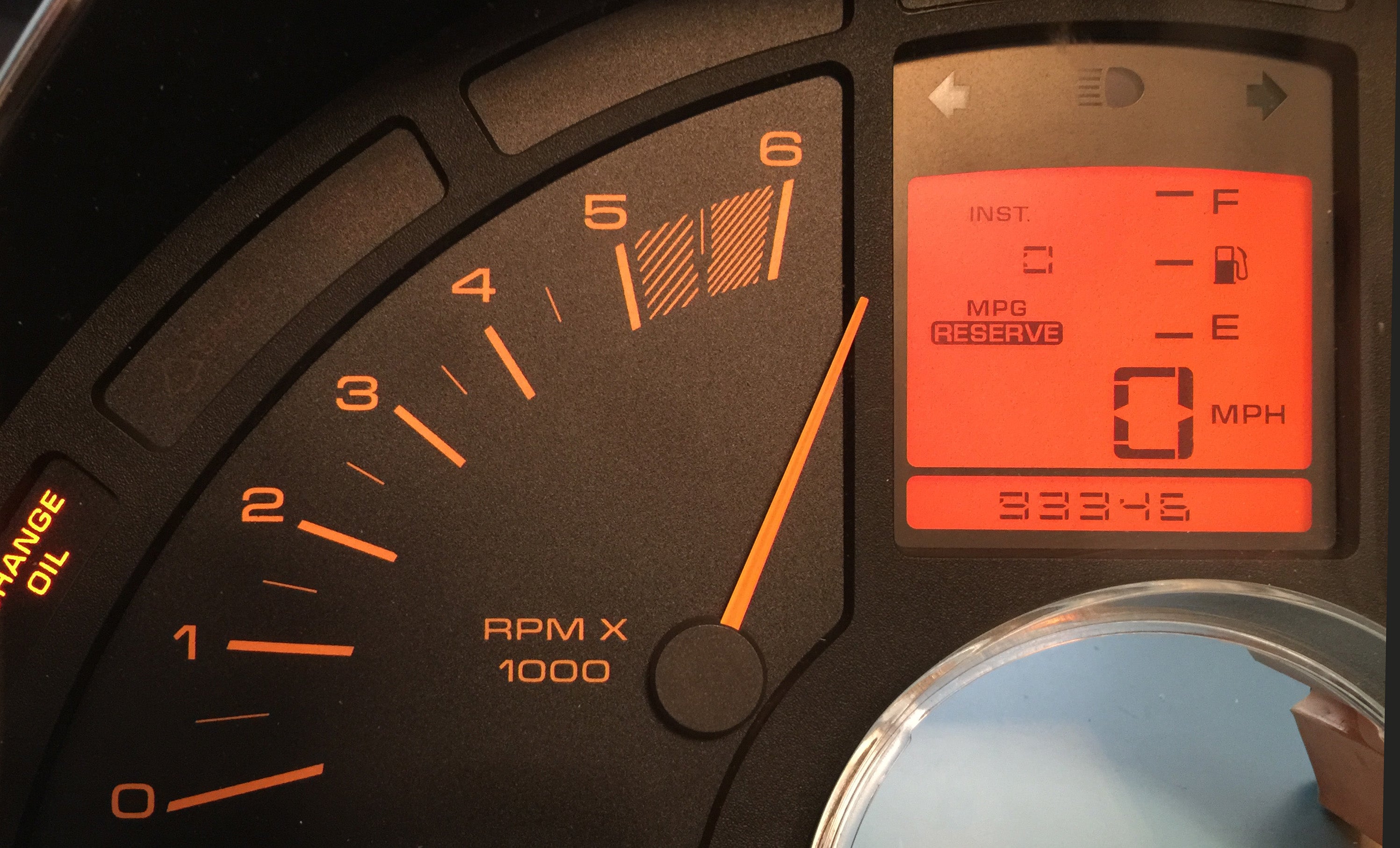
When the key is turned on, the tach needle pegs 6,000RPM (or 8,000RPM), then falls back below 0.
-
When the key is turned on and the engine is not running, the needle should read 0. If it doesn't, the analog IC has likely failed.
-
Your tachometer is inaccurate by more than a few hundred RPM
-
Not all defective Analog ICs look bad, but if yours looks like the one below, it's a sure sign the IC has failed:

Example of burned out IC
Analog IC Replacement Instructions
Supplies you'll need for this project
-
Analog Calibration IC - Click Here to buy.
-
Optional Bulb Kit - Click Here to buy.
-
7/32" nutdriver or Torx 15 screwdriver
-
Wire Cutters
-
A 15-25W soldering iron
-
Desoldering braid
Video of the repair
- Free Video of this repair - Click Here
Disassembly


Using a 7/32" nutdriver or Torx bit, remove the six screws holding the protective cover (circled in red in the images above).

Remove the protective cover and set it aside.

Carefully lift the top of the LCD until the pins release from the socket. Then slide it up and away from the plastic tabs holding the bottom of the display.

Remove the rubber gasket and translucent color filter.

Replacement

Factory Calibration IC to Replace
Using the solder braid, solder vacuum, or another desoldering device of your choice, remove the solder from the factory calibration IC pictured above
Pin 1 of the new IC is marked "1". Pin 1 of the board is sometimes marked and sometimes not, but it is always at the top of the board, which is the rounded side of the board. Install the IC on the side of the board without the tinned copper traces.
Solder the new IC in place using the supplied solder.

Orientation to install new IC

Orientation to install new IC
Note: It is sometimes necessary to gently move the capacitor (the cylindrical component pictured in images 5 and 6) upward to make room for the IC. If your capacitor breaks, we included a replacement in the kit. Match up the positive marking on the capacitor as shown in the image below.

Orientation to install new capacitor, if needed
Reassembly
Assemble the restored LCD panel, rubber gasket and color filter as shown in the image above.

If you're replacing the LCD connector, do that at this time.
Carefully slide the bottom of the LCD into the plastic housing.

Line up the pins of the display with the holes in the socket.

Slowly press the LCD into place, making sure that the top right corner clears the plastic tab shown in red in the image above.
Replace the protective housing and install the 6 screws removed in step 1.