1984-1989 Corvette Cluster Component Repair Kit
The component kit includes parts to fix many common and not-so-common problems with th 84-89 Cluster, including:
- Speedometer / Tachometer always reads "0"
- Cruise Control won't set
- Power Supply doesn't get turn-on signal when power is applied
- The 4.7V or 8.2V Zener-based power supplies aren't working
- the car has experienced a reverse polarity or 24V jump start
- A crystal or transistor has broken away from the board
- One or more modes (modes are selected by switches on the digital info center) do not work, or the engine info LCD panel is blank.
If you've replaced the board connector and photocell components and there's still an issue, this is the place to start!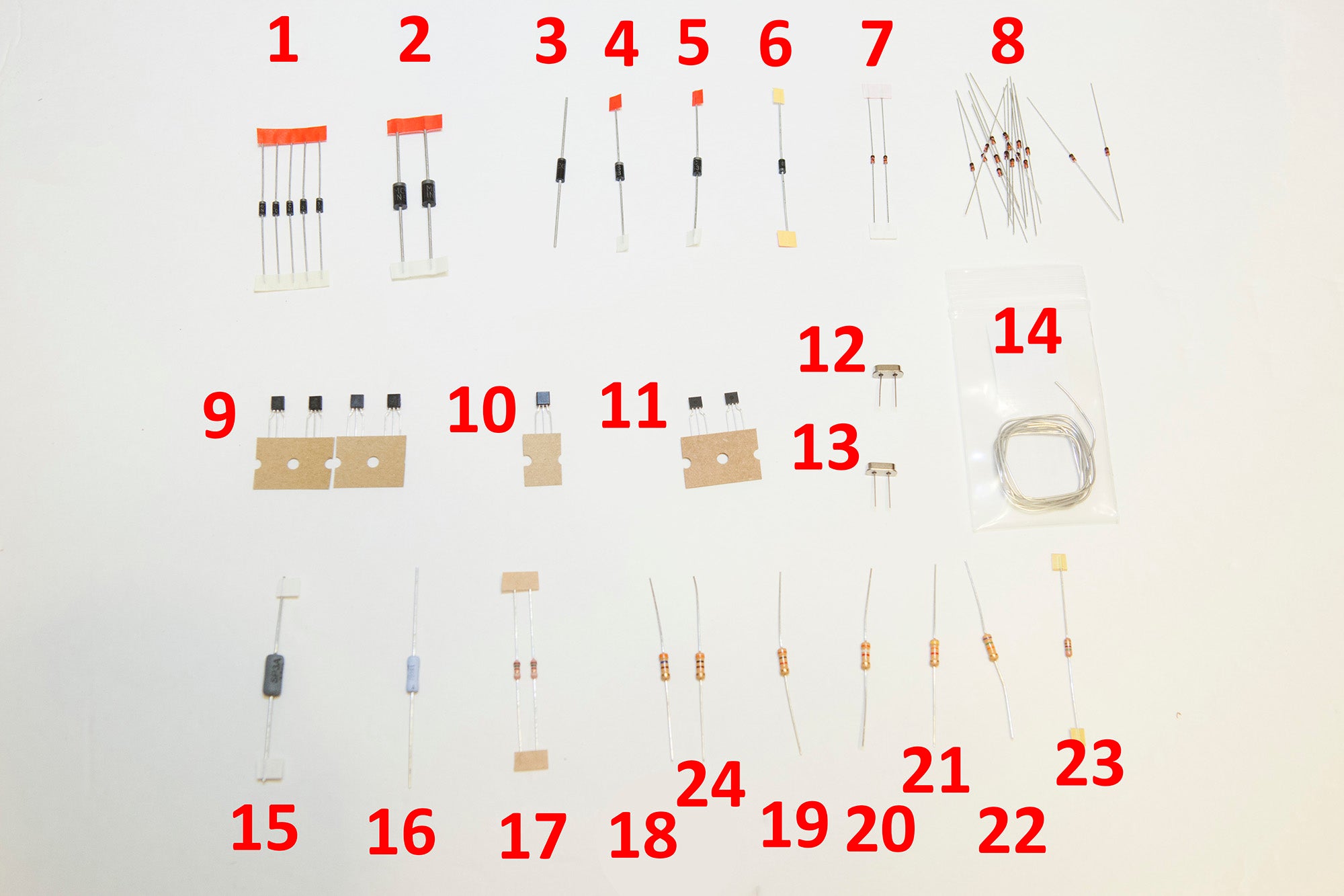
Instructions include a map of where every component is located!

Layout of a 1989 Board

Early Cluster Logic Board Layout

Locations for 87-89 boards

Locations for 84-86 boards
What you'll need to service the Digital Cluster
- 84-89 Component Kit [Click Here]
- Wire Cutters
- A Soldering Iron
- A way to desolder - use desoldering braid or a vacuum solder removal tool
- A digital Multimeter [Click Here]
- Optional: Static Wrist Strap
Links
Schematics (early) - Click Here
Schematics (late) - Click Here
Contents
- 1: CR2/CR5/CR17/CR17 (different on older models)
- 2: CR5/CR6 ( Unmarked/D13 on older models)
- 3: CR8 (Unmarked on older models)
- 4: CR39 (CR112 on older models)
- 5: CR1 (D1 on early models)
- 6: CR9 (CR5 on older models)
- 7: CR4/CR52 (CR52 not used on early models)
- 8: CR11/12/13/14/15/16/19/20/21/22/23/24/25/26 (unmarked on older models)
- 9: Q2/Q6/Q7/Q8 ( on older models)
- 10: Q5 (Q8 on older models)
- 11: Q11/Q14 (Q106/Q108 on older models)
- 12: 4.000MHz Crystal (Cruise)
- 13: 4.194MHz Crystal (CPU)
- 14: Lead/Tin Solder Packet
- 15: R146 (R172 on older models)
- 16: R74 (R55 on older models)
- 17: Unused, deleted from future kits
- 18: R97 (R203 on older models)
- 19: R63 (R52 on older models)
- 20: R65 (R51 on older models)
- 21: R47 (R32 on older models)
- 22: R48 (R34 on older models)
- 23: R49 (R33 on older models)
- 24: R75
- 60/40 Tin Lead Rosin Core solder (don't use acid core or lead-free solder on the cluster!)
Removing the Digital Cluster
Follow the removal instructions located [here]
Disassembling the Cluster
Disassemble the cluster using the documentation
[Click Here]
Warning! Avoid removing the bottom board if at all possible! It's a huge
amount of labor, and the potential for damage to the LCDs is fairly high if you don't follow instructions! If you do, follow the directions [here] to disassemble, and [here] to reassemble.
Checking the 4.7V Power Supplies
- Measure the voltage across CR4 (component 7 in the images above). It should be 4.7-5.0V. If not, replace components 7 and 9 and 24, and Component 1 (the one marked CR2).
- If your cluster is an 87-89 model and has a CR52, measure the voltage across it (also component 7). It should be 4.7V - 5.0V. If not, replace components 7 and 16.
Checking the 8.2V Power Supply
- Measure the voltage across CR9 (CR5 on older modens). This is component 6 above. It should be 8.0-8.2V. If not, replace components 6 and 16.
<strong>If the speedometer constantly reads "0", do the following</strong>
- Measure the voltage across R49 (R33 on older models). If it's higher than 1V, replace it (component 23).
- Replace Component 1 / CR2
- Replace Component 24 / R75
- Replace Components 21 and 22
- Replace Component 5 / CR1.
- Consider checking / replacing U8 (not included) if this doesn't work.
- Consider checking / replacing U7 (Not Included) if this doesn't work.
If the tachometer constantly reads "0", do the following:
- Replace Component 20 / R65
- Replace Component 1 / CR5
- Replace Component / R63
- Replace Component 9 / Q2.
- Consider checking / replacing U8 (not included) if this doesn't work.
- Consider checking / replacing U3 (not included) if this doesn't work.
If the power supply is not turning on, do the following:
- Measure voltage between pin 3 and 8 of the power supply connector. It should be 2.1V or higher. If not, the power supply has detected a fault and needs to be replaced.
- Measure voltage between pin 4 and 8 of the power supply connector. It should be 0.3V or lower to turn the power supply on.
- Measure the voltage across CR4 (component 7 in the images above). It should be 4.7-5.0V. If not, replace components 7 and 9 and 24, and Component 1 (the one marked CR2).
- If your cluster is an 87-89 model and has a CR52, measure the voltage across it (also component 7). It should be 4.7V - 5.0V. If not, replace components 7 and 16.
- Consider replacing U12 (not included) if this doesn't work.
If the cluster tests OK on the bench, but not in a car, do the following:
- This is likely caused by faulty CR4. Measure the voltage across CR4 (component 7 in the images above). It should be 4.7-5.0V. If not, replace components 7 and 9 and 24, and Component 1 (the one marked CR2).
If the CPU crystal is damaged, do the following:
- Replace component 13 / Y1 with the 4.194MHz crystal
If the Cruise crystal is damaged, do the following:
- Replace component 12 / Y2 with the 4.000MHz crystal
If the car has experienced a reverse polarity or 24V jump start, do the following:
- Replace components 1-10.
If one or more of the Engine Info LCD panel displays is not working, do the following:
- Replace Component 10 / Q5 and All 14 diodes marked by Component 8.
- If that doesn't work, consider checking/replacing ICs U4/U5 (not included)
- If that doesn't work, consider checking/replacing IC U3 (not included)
If the cruise is not working, do the following
- Check the cruise solenoid for shorts. If the solenoid is shorted, the new transistors will be destroyed. Replace if shorted.
- Check the 8.2V power supply as shown above. Fix if needed.
- Replace component 11 (both transistors).
- Replace component 12 / Y2 with the 4.000MHz crystal
Reassembling the Cluster
Note: If you removed the bottom board, follow
[this process] exactly to replace it before proceeding.
Reassemble the top board of the cluster using the documentation located
[here]