1990-1996 Corvette Trip Monitor Restoration
90-96 Digital Information Center / Trip Monitor Restoration

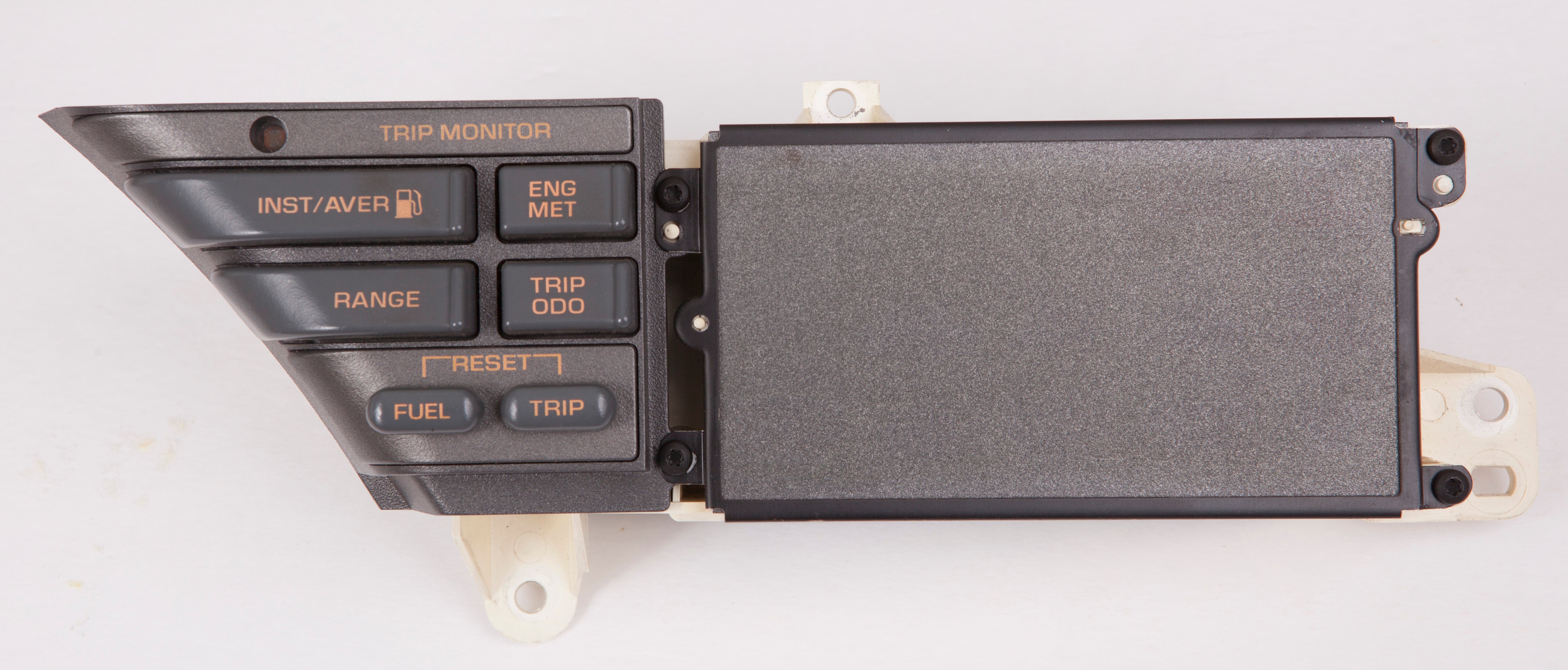
Figure 1 - DIC Overview
Parts
- 90-96 Trip Monitor Restoration Kit - Click Here to Purchase
or
- 90-96 Trip Monitor Photocell Dimmer Kit - Click Here to Purchase
- 90-96 DIC Bulb Kit - Click Here To Purchase
Tools Required
- Torx 15 screwdriver/bit
- Small Flat Blade screwdriver
- Small Phillips Screwdriver
- Sharpie
- Xacto Knife
- Soldering Iron (30-40W)
- A method of removing solder (desoldering braid or vacuum solder removal tool)
Video of the restoration
Disassembly
Warning! Disconnect the positive battery cable before disconnecting the Digital Info Center. Failure to do so will set codes related to seat belts and INFL RESET lamps!
1. Using a Torx T-15 screwdriver, remove the five screws holding the switch panel to the DIC housing. There are four screws on the front side, and one on the back.

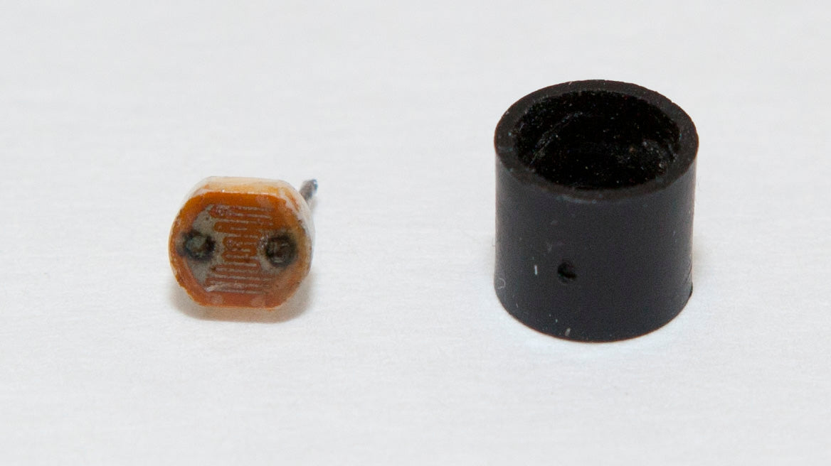
Figure 2 - The Photocell

Remove the four T15 screws from the front and set the metal frame aside

Remove the fifth T15 screw from the rear, then remove the black button assembly.


- Remove the six Phillips screws from the rear of the button assembly and separate the halves of the black case.

Carefully unclip the photocell circuit board from the black case to expose the solder joints of the photocell.

Bulb Replacement

3. Using the Sharpie, mark the locations where the factory warning/indicator bulbs (the ones in rectangular grey sockets) are located. Remove the bulbs from the DIC housing by twisting 1/16 turn counterclockwise and gently pulling the bulb away from the plastic circuit board.

4. Remove the round brown and grey illumination bulbs from the switch panel by turning approx 1/16 turn counterclockwise with a small flat-blade screwdriver and gently pulling the sockets away from the switch panel. Use needlenose pliers if needed.


5. If your kit included bulbs with the plastic bases installed, skip to step 11. If they didn't, continue to step 6.
6. Using an Xacto knife or other pointy tool, unwind the old bulbs from the brown and grey sockets and set them aside.

7. Insert the bulb marked BROWN in the brown socket. Make sure that there is only one lead in each hole of the socket to prevent shorts.

8. Bend each lead sideways, following the channel cut into the plastic socket.


9. Wind each of the two leads around the rectangular side post on the edge of the socket counterclockwise, again following the channels cut into the plastic socket. Then trim the lead as shown above.


10. Repeat steps 6-8 for the GREY socket and bulb marked GREY. Note that the replacement bulb is smaller than the factory grey bulb, and it will sit lower in the socket.

11. Reinstall the brown socket in the hole marked BROWN on the rear of the switch panel. Turn approx 1/16 turn clockwise with a small flat-blade screwdriver.

12. Replace the switch panel in the DIC plastic housing and reinstall the five T-15 Torx screws. Next, gently reconnect the 5 pin electrical connector to the switch panel. Make sure the connector is properly aligned to the pins and that there are no pins sticking out on either side of the electrical connector.
13. Install the new warning/indicator bulbs in the back of the DIC plastic housing in the locations you marked with the Sharpie, leaving the non-marked holes empty. Make sure the metal tabs of the sockets remains outside the hole for the bulb so that they make contact with the plastic circuit board. Only install bulbs where bulbs were located before.
90-96 Photocell Repair
Dimmer Circuit Behavior
With the headlights off, the headlight dimmer control has no effect - the Photocell alone controls the brightness of the cluster. The bulbs should be at full brightness on a sunny day, medium brightness on a cloudy day, and low brightness at night or when the photocell is covered.
With the headlights on, both the headlight dimmer and the photocell control the brightness of the cluster. In general, the bulbs should be at full brightness on a sunny day, medium brightness on a cloudy day, and low brightness at night or when the photocell is covered - plus or minus any adjustment dialed in via the headlight dimmer. The headlights should dim when the headlight control is rotated to the Dim setting, and should get brighter when it is rotated to the Bright setting.
Photocell Replacement
1. Desolder the photocell connections and remove the photocell and light guard assembly.

2. Use an Xacto knife to remove any glue that might be holding the photocell inside the housing. Then remove the photocell from the cylindrical black housing.

3. Insert the new photocell into the black housing with one lead in each hole in the plastic housing.
4. Insert the two leads into the board and solder the photocell in place.
5. Trim away the extra length of photocell leads with the wire cutters.
90-96 Trip Monitor Switch Replacement
Note: As of March 2020, this is becoming increasingly problematic. Consider replacing your switches even if they're working correctly right now.
Over time, and especially with liquid spills, the switches become high resistance. Unfortunately, the computer uses resistance to determine which button is pressed, and when the switches wear, the computer interprets the switch presses as an incorrect function, or as no press at all. The solution is to replace all switches. The restoration kit includes all six switches.

The switches we'll be replacing

1. Using the method of your choice, remove the solder on each of the four posts of each of the six switches

2. Remove the six old switches and keep them separate from the new switches.

3. Place the new switches in the circuit board. Note that switch 3 is turned 90 degrees from the other switches. Make sure to mount the new one that way, too.

4. Solder each of the six switches to the circuit board.

5. You can clean resin from the circuit board with some isopropyl alcohol and an old toothbrush.

The finished circuit board
Reassembly
Reassemble the Digital Information Center by reversing the disassembly steps above.
Testing and Reinstallation
Before completely reassembling the car, take the time to test your work. Plug the DIC in, and test the lighting and other functions of the panel. When you are satisfied that everything is working, reinstall the panel and replace the trim.
